Liquid Rocket Engine Design
Designed and Created on Fusion360 by Chabod Masere
1. Design Intent
I designed this liquid rocket engine as a conceptual thrust chamber assembly intended to reflect realistic propulsion-system architecture rather than purely aesthetic modelling. The objective was to demonstrate system-level understanding of injector–chamber–nozzle integration, cooling-driven geometry, and structural realism consistent with NASA liquid rocket engine design methodology.
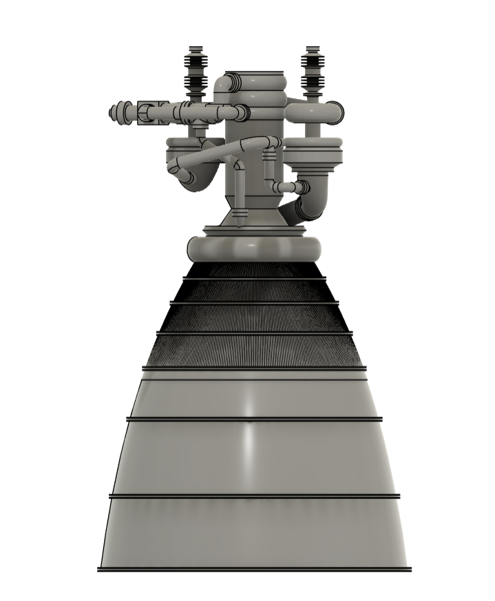
The CAD model shown in Figures 1–3 serves as a foundation for analytical sizing, thermal evaluation, and injector refinement following established NASA propulsion design practices.
2. Analytical Framework (NASA-Based)
The design approach follows classical liquid rocket engine analysis as documented in NASA propulsion literature. Thrust production is governed by [1], [5]:
where thrust is a function of propellant mass flow rate, exhaust velocity, and nozzle exit pressure relative to ambient. These relationships informed the overall chamber proportions and nozzle expansion geometry visible in Figures 1 and 3.
Thermal constraints were considered using NASA heat-transfer guidance, where convective heat flux at the chamber wall is expressed as [7]:
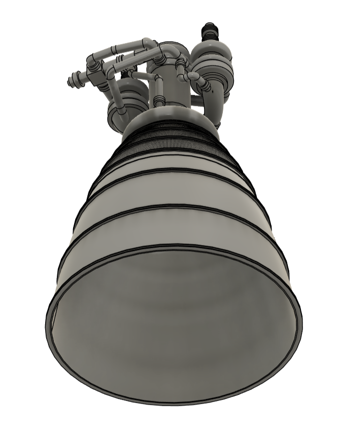
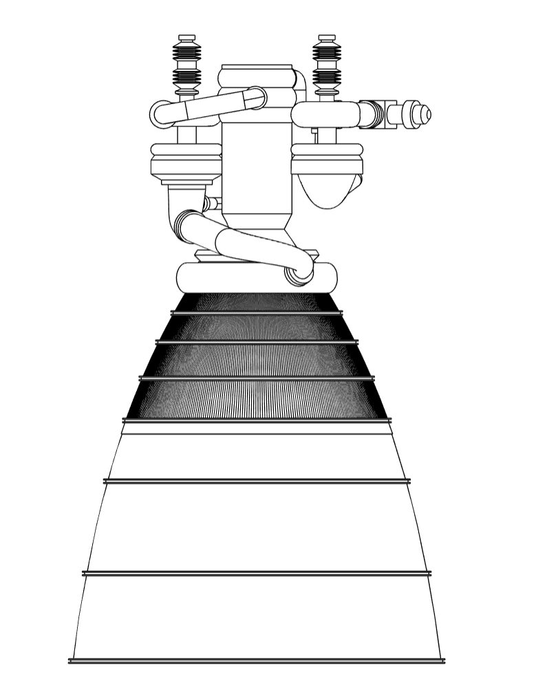
This framework directly influenced chamber wall thickness, throat-region volume, and the segmented external geometry shown in Figures 2 and 3.
3. Engine Configuration and Injector–Feed System
The overall engine configuration shown in Figures 1–3 consists of an injector/manifold assembly, a cylindrical combustion chamber, and a converging–diverging bell nozzle. The proportions were selected to be representative of a small- to medium-class liquid rocket engine, consistent with scaling relationships described in NASA propulsion references [1], [5].
The injector region, visible in Figure 2, is designed as a structural and functional interface between the propellant feed system and the combustion chamber. While individual injector elements are not explicitly modelled at this stage, the injector body geometry and manifold volumes are consistent with multi-element injector concepts such as impinging or coaxial injectors discussed in NASA injector design literature [2].
External feed plumbing was routed with realistic bend radii, spacing, and component separation, avoiding idealised symmetry. This reflects practical packaging constraints seen in operational engines, where manifolds, valves, and instrumentation must coexist within limited spatial envelopes [1].
The wireframe view in Figure 3 confirms smooth geometric continuity and clean topology, suitable for subsequent refinement into injector faceplate detailing, combustion stability analysis, and thermal modelling.
4. Combustion Chamber, Throat, and Nozzle Design
The combustion chamber and nozzle geometry shown in Figures 1–3 were developed with thermal and structural constraints as primary design drivers. NASA thrust chamber design criteria identify the throat region as the dominant heat-flux location and a key determinant of cooling strategy and wall thickness [3], [7].
The segmented external geometry visible in Figures 2 and 3 is compatible with regenerative or jacket-based cooling approaches, preserving sufficient wall thickness to accommodate internal cooling channels or liners. While the specific cooling method is not explicitly modelled in this iteration, the geometry was intentionally designed to allow realistic cooling integration without major redesign.
The bell nozzle profile shown most clearly in Figure 1 follows a smooth contour consistent with NASA bell-nozzle optimisation practices [5]. Abrupt curvature changes were avoided to minimise boundary-layer separation risk and thermal stress concentrations. The nozzle expansion length represents a practical compromise between performance and structural mass, suitable for atmospheric or near-atmospheric operation.
Particular attention was given to the throat region, which experiences the highest combined thermal and mechanical loading. The geometry preserves sufficient volume for throat reinforcement or inserts, acknowledging NASA findings that throat thermal limits often define thrust chamber life and performance margins [7].
5. Structural Load Path and Integration
The upper chamber region provides a natural interface for a thrust mounting flange or structural skirt, through which axial thrust loads would be transmitted into a vehicle structure or test stand. NASA design practice treats the thrust chamber as both a propulsion and structural component, subject to combined pressure, thermal, and mechanical loading [3], [5].
Although not explicitly modelled in this iteration, the geometry shown in Figure 2 supports straightforward integration of bolt-circle flanges or thrust frames in future design stages.
6. Design Status and Next Steps
This engine represents a conceptual but technically grounded propulsion design. The CAD model is suitable for progression into preliminary design through:
- explicit injector element definition and combustion stability analysis,
- regenerative cooling channel modelling,
- chamber pressure and thrust back-calculation from geometry,
- throat-region thermal stress analysis, and
- structural interface and fastener detailing.
The intent of this work is to demonstrate propulsion-system design thinking grounded in established aerospace methodology rather than purely visual representation.
References (IEEE — NASA)
[1] G. P. Sutton and O. Biblarz, Rocket Propulsion Elements, 7th ed., New York, NY, USA: Wiley, 2001.
[2] C. Chambers, Liquid Rocket Engine Fluid-Cooled Combustion Chambers: Design Criteria and Recommended Practices, NASA, Washington, DC, USA, 1973.
[3] D. R. Batha, Thrust Chamber Cooling Techniques for Liquid-Propellant Rocket Engines, NASA Technical Report, 1963.
[4] NASA, Space Vehicle Design Criteria: Regenerative Cooling, NASA SP-series publication.
[5] D. K. Huzel and D. H. Huang, Design of Liquid Propellant Rocket Engines, NASA, Washington, DC, USA, 1967.
[6] NASA Glenn Research Center, Liquid Rocket Engine Fundamentals, NASA Technical Notes.
[7] K. J. Kacynski, Wall Heat Transfer and Cooling Limits in Rocket Throat Regions, NASA Technical Memorandum, 1990.