CubeSat Platform
Created by Chabod Masere on SolidWorks
1. Overview
This CubeSat was developed as a flight-representative small-satellite platform, with emphasis on structural clarity, deployable power generation, and disciplined subsystem packaging. Rather than treating each subsystem independently, the design focuses on how structure, avionics, power, payload, and external interfaces coexist within the dimensional and mechanical constraints imposed by the CubeSat standard.
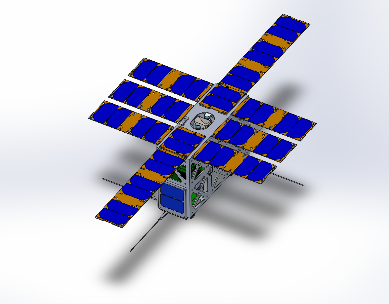
The configuration shown in Figures 1–6 represents a complete spacecraft layout suitable for low Earth orbit (LEO) missions, with explicit accommodation for avionics, deployable solar arrays, antennas, and a nadir-facing payload interface.
2. Structural Configuration and Load Paths
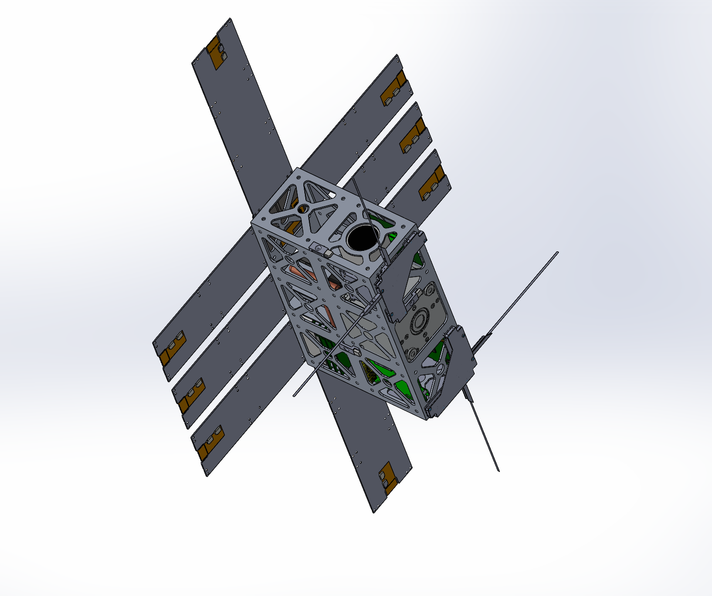
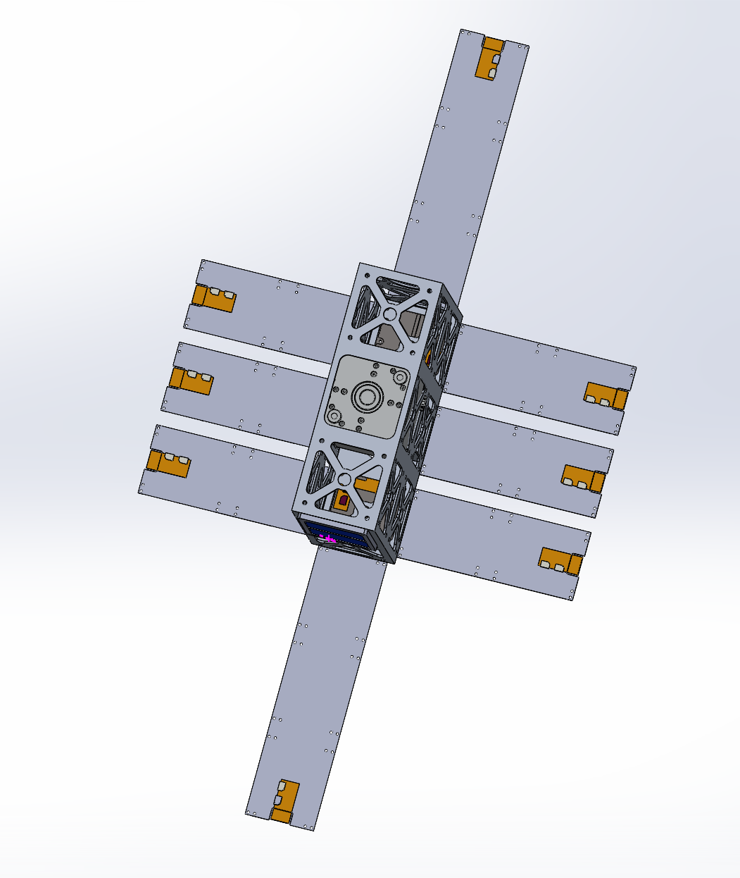
The spacecraft bus adopts a central load-bearing frame, visible in Figures 3, 4, and 6, which serves as both a mechanical backbone and a reference for subsystem integration. The frame provides continuous load paths between the launch vehicle interface, internal avionics stack, and deployable appendages.
An open-frame architecture was selected over a closed-box design to improve:
- internal accessibility during integration and testing,
- visual inspection of deployment mechanisms, and
- thermal coupling between subsystems and external radiating surfaces.
This approach reflects common lessons from CubeSat programs, where late-stage integration constraints often dominate overall mission risk rather than individual component performance.
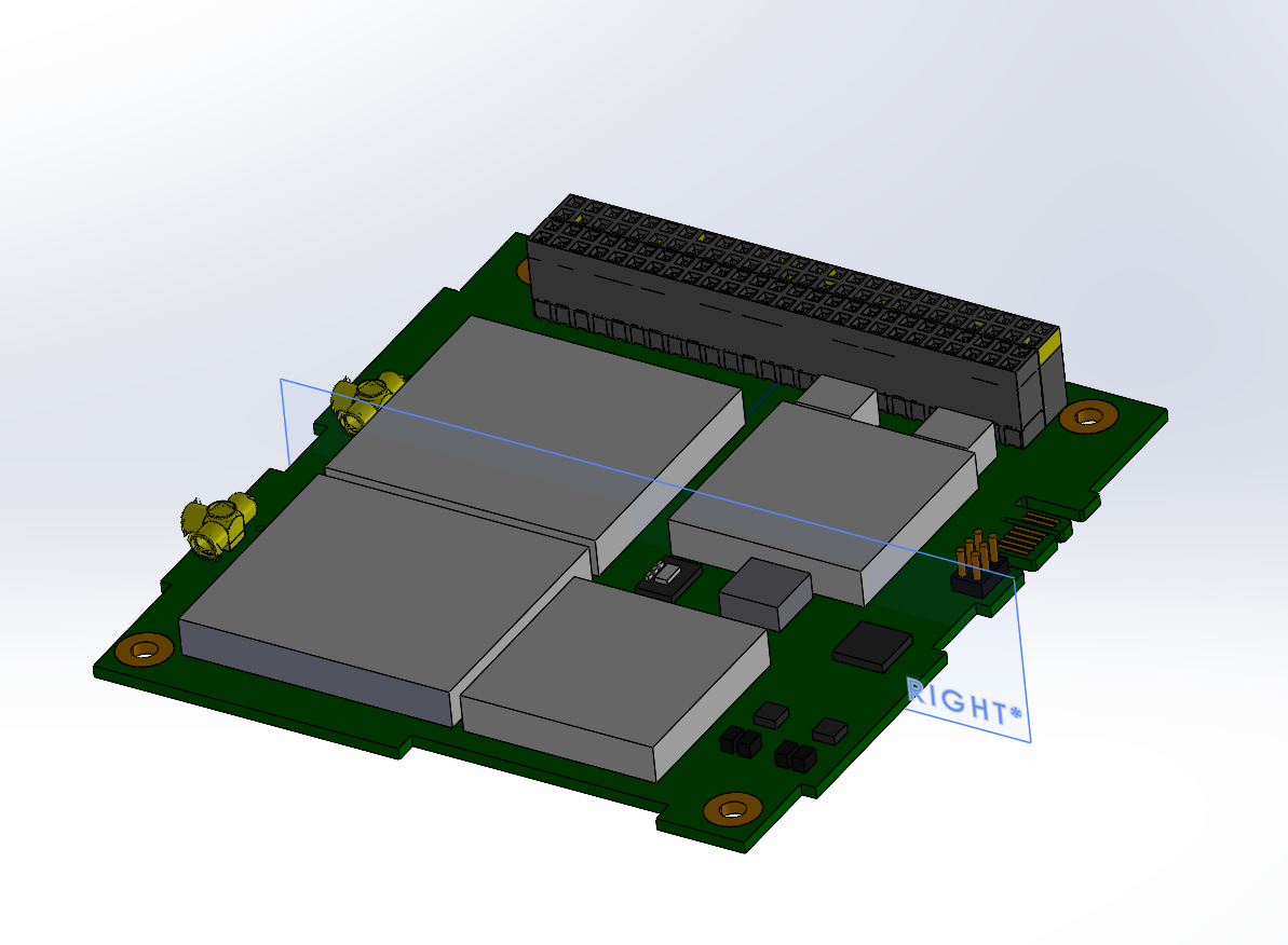
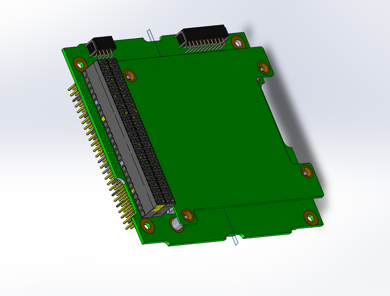
3. Avionics Architecture and Internal Layout
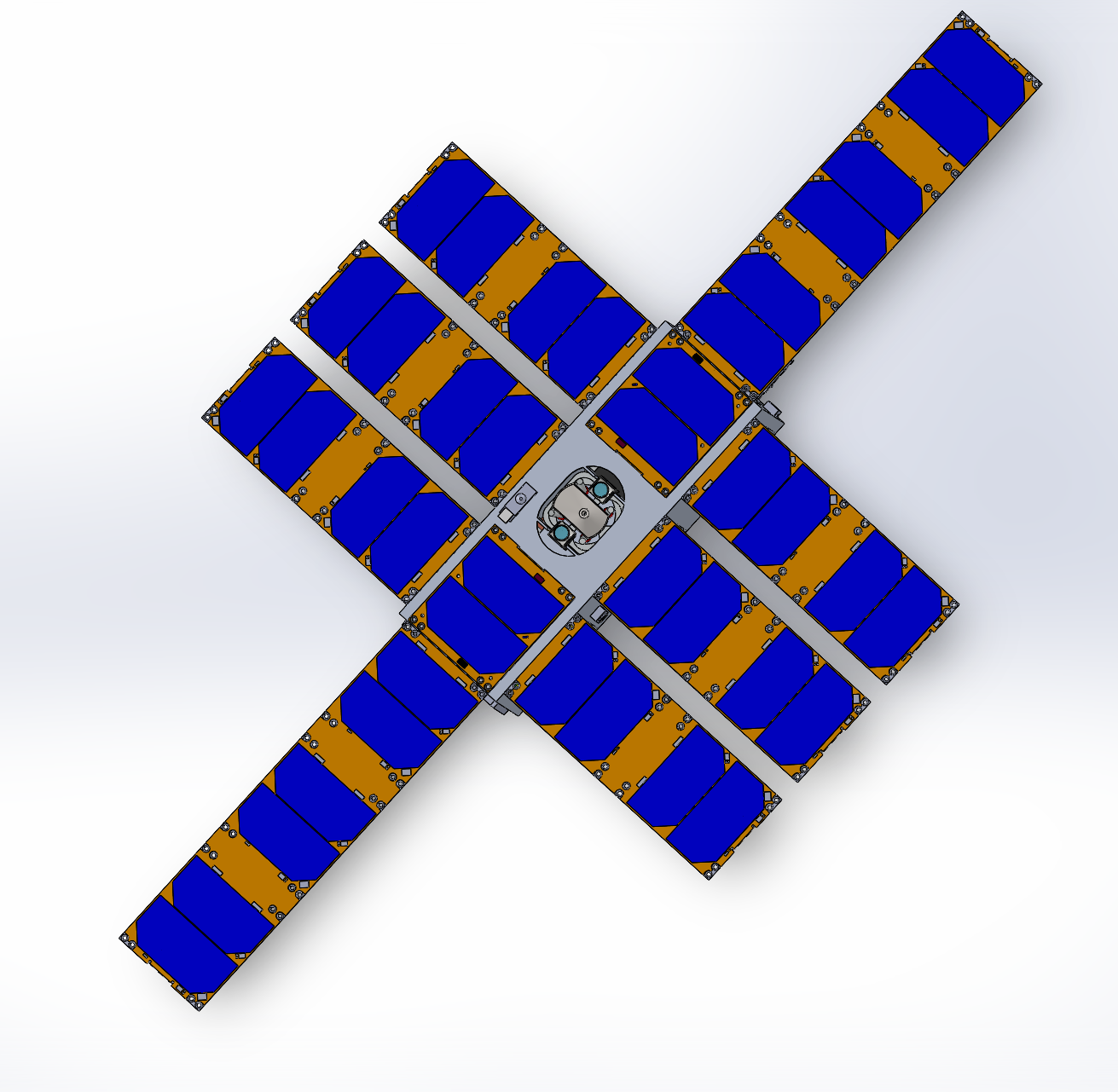
The avionics subsystem, shown in detail in Figure 2, is implemented as a stacked PCB assembly using a high-density board-to-board connector. This configuration reduces harness complexity, improves vibration robustness, and enables modular separation between functional subsystems such as power management, onboard computing, and communications.
The internal layout shown in Figure 6 was arranged to:
- keep avionics clear of solar deployment envelopes,
- avoid obstruction of the payload aperture, and
- maintain physical separation between high-power and low-level signal electronics.
By enforcing mechanical separation at the layout stage, the design reduces coupling between deployment events and avionics reliability.
4. Deployable Solar Array System
Electrical power generation is achieved through symmetrically deployed solar array wings, as shown in Figures 1, 3, and 5. The array geometry increases available solar collection area while maintaining deployment balance about the spacecraft centre of mass.
Deployment symmetry was a deliberate design choice to:
- minimise disturbance torques during panel release,
- simplify post-deployment attitude recovery, and
- reduce reliance on immediate active control following separation.
The available electrical power can be estimated using the standard spacecraft power relationship:
where η is the solar cell efficiency, A is the illuminated panel area, and G is the solar constant. The panel segmentation visible in Figure 5 reflects realistic cell tiling, mounting, and hinge constraints consistent with flown CubeSat arrays.
5. Payload, Antennas, and External Interfaces
The nadir-facing configuration shown in Figure 4 defines the primary payload interface and antenna deployment orientation. External interfaces were positioned to avoid interference between:
- payload field-of-view,
- antenna radiation patterns, and
- solar panel deployment paths.
By separating mission-critical surfaces from deployable mechanisms, the design reduces coupling between mechanical events and mission performance. Antenna placement was chosen to maintain clear radiation paths while remaining mechanically protected during launch and deployment.
6. Design Maturity and Applicability
This CubeSat represents a system-complete spacecraft architecture rather than a conceptual layout or isolated subsystem model. The CAD model directly supports downstream activities such as:
- mass and centre-of-gravity estimation,
- power budget development,
- deployment dynamics assessment,
- thermal modelling, and
- launch vehicle interface verification.
The intent is to present a CubeSat platform that is credible, integrable, and scalable, suitable for adaptation across a range of small-satellite mission profiles.
References (IEEE — CubeSat / NASA / Standards)
[1] California Polytechnic State University, CubeSat Design Specification, Rev. 13, 2014.
[2] NASA Ames Research Center, Small Spacecraft Technology State of the Art, NASA/TP-2014-216648, 2014.
[3] J. R. Wertz, D. F. Everett, and J. J. Puschell, Space Mission Engineering: The New SMAD, Hawthorne, CA, USA: Microcosm Press, 2011.
[4] NASA Jet Propulsion Laboratory, Design Principles for Small Satellite Missions, JPL Technical Reports.